I was recently contacted by a newer member of the LEGO Train community asking for information on the various types of curve tracks used in PennLUG. My response was a lengthy email, which has been adapted to fit an article format, and will be the content of this article.
Before I begin, I should briefly touch on some of the standards for LEGO track configurations. More information can be found on Michael Gale’s L-Gauge.org. Standard spacing practices for most layouts (including my own PennLUG) use a 16-stud spacing between the centerlines of two parallel tracks. There are two main reasons for this standard. One, it was set by LEGO, when they produced the 9-volt switch tracks. Using a turnout, a return curve, and an extra length of straight track, you get two even and parallel tracks. Two, this yields a convenient way to build track: two lines evenly spaced on one baseplate.
Two parallel tracks and a standard LEGO turnout demonstrating the 16 stud centerline distance.
Every LEGO train enthusiast has probably, at some point, owned a loop of standard LEGO track. Any number of straight sections closed off by the small curve tracks you’d find in any 9-volt of Power Functions set. These tracks are known as “R40”, as they have a radius of 40 studs.
Young and new recruits to the LEGO train scene will never have known anything other than the current generation of power functions. Battery packs coupled with infrared receivers and remote controls, each taking up precious space in your build. However, it didn’t used to be this way. The previous generation of trains (ignoring the aborted RC train theme) used metal rails to directly power the motors. Both generations had their own advantages and disadvantages, which I will attempt to shed some light on. In a follow up article, I will go over some advanced applications of each, and hybrids that combine the best of both technologies.
Batteries take up space. In my eye, this is Power Function’s main drawback. Additionally, the current generation Infrared (IR) Receiver is quite large and the sensor on it needs to be visible from outside the locomotive for the signal to reach it.
IR Receiver with the shell removed. Why is this thing so big?
Trying to incorporate the AAA/AA battery pack and the IR Receiver into a model is often very tricky, especially when working with 6 or 7 stud wide models. Additionally, batteries need to be recharged or replaced after several hours, so the battery pack needs to be accessible or removable. When running for many consecutive hours at a convention, swapping batteries becomes a chore. For home use, it is not such a big deal. The IR receiver also has difficulty reaching more than a few feet when there aren’t any walls or ceiling to reflect the light off of. On the other hand, the IR receiver and battery boxes are still currently in production, which means they’re cheap.
PF track Vs. 9V track
Track power has always been my preference and I’ve iterated through several generations of electrical systems searching for the best configuration. LEGO’s classic 9V train controller is simple, turn the knob and your locomotive starts to move. The biggest limiting factors are being limited to metal equipped track and the original 9V train motor, (meaning no double crossovers). Additionally, laying out certain track geometries will cause short circuits. Also, once your loop gets to a certain length, additional power hookups are required so as to avoid slow downs. Of course, the main drawback is price. Expanding or building a new 9V layout is very costly. 9V straight track hasn’t been manufactured in almost 10 years and averages $3.50 each used and $5.50 new on the aftermarket. Original 9V train motors average $35 each used and $75 new. Many clubs still use 9V systems, and with ME Models finally shipping their metal track, will continue to do so for years to come.
Things start to get interesting when you get rid of LEGO’s speed controller and start substituting your own electronics. Swap in the third party Bluetooth controlled SBrick in lieu of the IR receiver and not only save space, but also gain control range, gain 2 more channels for a total of 4, and lose the line of sight requirement.
2 Channel PF IR Receiver3rd party SBrick, approx 8x available power output in a smaller footprint
Get rid of the LEGO 9V train controller and use constant track power to feed a Bluetooth motor controller. No batteries! Or better yet, use batteries and track power together: constant track power feeding a Bluetooth motor controller, with batteries for backup. With such a system, a track powered locomotive can continue through double crossovers, over draw bridges, maintain consistent speeds through spotty connections on dirty track, or possibly even charge itself. With the track providing power most of the time, the batteries will rarely need to be recharged.
Read about my experiments in hybrid systems in depth in my next article.
I’m making slow and steady progress on the layout.I want to get the basic terrain, track, and ballast down so I can start operating the layout as quickly as possible.After that I can worry about landscaping, buildings, and other details.This will help me stay motivated to completion, because what’s the point of having the trains if we can’t play with them?
Examples of basic MILS rails modules used by NELTC
I participate in a club that uses the Modular Integrated Landscaping System (MILS) for rapidly assembling layouts at shows.In addition to making layouts a snap [1], the modules also provide some depth to the terrain and provide ways to hide wiring.We have some general guidelines for incorporating rails into the modules, similar to the PennLUG baseplate standard, though differing in that we always want half a baseplate between the viewing edge and mainline.
I’m diverging slightly from the standard ballast profile of the club guidelines because looking at historical photos of the yard, the tracks ran at ground level.Yet, I need to maintain the same rail height for club layout compatibility. That means the ground level ends up being twice as high as the MILS standard and each of these modules ends up consuming twice as many bricks.I can already see the payoff with the canal that runs through the yard and the extra brick of height gives the right feeling of depth.
After the previous post on Ararat 1972 and Cale’s piece on Brick Model Railroading as such, I think the pieces are now set for the next installment in the series of inspiring layouts: Corfe Castle Station by Carl Greatrix. Lately, Carl has been the guy who has brought you the Caterham Seven and a lot of the visuals in the recent Lego games, but next to this, he is also a real trainhead and a lover of Scale Modelling. With the Corfe Castle Station layout, he had decided to fuse both of these to create an unique layout.
Corfe Castle Station – the eye-catcher and starting point of the layoutThe (almost finished) layout at STEAM 2011
The first thing that you notice when looking at Corfe Castle Station is that it follows a typical “British” approach. At least, that’s how it looks like for me after having read so many British Model Railroading Magazines (like Railway Modeller) when I was young. This means that we are looking at two mainline tracks and a siding, with a station as the main visual element. In fact, it’s just a very big diorama. The layout is an oval of which more than half is the fiddle yard and thus not part of the diorama. So, just as with Ararat 1972, there is no large yard where you can show off your trains. However, it does have two continuous loops which are ideal to show of your trains in high speed!
Overview of the layout – Two ovals and a fiddle yard.
What sets this layout apart of most other Lego Railway layouts is the design choices he makes: instead of using studs everywhere, Carl uses Scale Modelling techniques for making roads, gravel and mountains. This means that not everything in this layout is made out of Lego! The effect works surprisingly well. Instead of looking like a layout made of Lego, this is a layout that uses Lego as one of its mediums.
An example of combining Lego with scale modeling techniques
It becomes even more interesting when inserting his trains. This is because Carl, unlike most Lego Train builders, tries to use as little selective compression as possible. The result are models that are so accurate, that they don’t even look out of place in an actual O-scale layout.
Carl’s trains in an O-scale layout. Not part of Corfe Castle, but too nice not to show.
As said, the layout not only uses Lego. Carl was nice enough to keep a diary over at Flickr in which he shows how he designed the whole layout. This gives us the great possibility to dive a bit deeper into the layout and the way how it’s build.
My next challenge was turning 7.5 miles of branchline into a realistic, operating, achievable layout plan.As with any era-specific model railroading project, I started with my historical references.In this case, primarily the Robertson and Davis’ book Grand Trunk 713 and the Lewiston Branch, but also Grand Trunk Heritage by Philip R. Hastings and Grand Trunk in New England by Jeff Holt.These were filled with images of trains operating in various points along the line and gave me ideas for the “scenes” I wanted to model along the line.Most of the line and places I want to model from the 1950s are still here today and I could turn to Bing to help me out.
I was able to identify 6 scenes that appeared in historical photographs and I think really captured the essence of the line.The idea is that any observer familiar with the branch could look at these places arranged together and identify the railroad I was trying to model without any explanation. I’m trying to keep the layout achievable, so for the near future I’m going to focus on the following two scenes:
Littlefields Crossing
Aerial view of Littlefields Crossing in Auburn, ME
The branch crosses a 120’ truss bridge over the Little Androscoggin river.In the early 1900s until the 1930s an electric tram service, the Portland Interurban Line, crossed the Grand Trunk tracks and over a stone arch spanning the river.The line was abandoned and a truss road bridge erected next to it, however the stone arch of the Portland Interurban is still there today and is used to carry pipes over the river.
If anyone knows a good technique to model an 80-stud wide stone arch like this, I’m all ears.
StreetView of the Littlefield’s Crossing bridge from Hotel Rd. The vegetation in the foreground is the stone arch of the Portland Interurban.
The Lewiston Yard
1. Lewiston Depot 2. Swift Meat Packing Plant 3. Freight Shed 4. Store House (Platform?) 5. Enginehouse 6. Armour and Company Meat Packing Plant 7. Freight Transfer Platform 8. Freight Transfer Platform 9. Hall and Knight Hardware Company Shed 10. Shed 11. Cross and Company Grain Mill 12. Max Millar Scrap Company 13. JB Skinner Coal Shed and Trestle 14. US Bobbin Company Shed 15. Oil Tanks 16. Lewiston Handle Company
As you can see from the yard diagram I’ve reproduced on the Bing map, the Lewiston yard was full of industries and operating potential.It could be (and may very well turn out to be) a layout in itself.There’s plenty of demand for all sorts of rolling stock whether its boxcars, refers at the meat packing plants, gondolas at the scrap company, tankers for the oil tanks, or hoppers at the coal trestle and engine shed. Within the yard the focal points are the enginehouse at the center and the depot at the east end.A canal bisects the yard providing a visual break and some varying elevation in an otherwise flat surface.
The track plan.
The 1st draft layout plan in BlueBrick
I opted to make Littlefield’s crossing my westernmost scene instead of the Androscoggin River Bridge.The Androscoggin River Bridge is about 360 feet long which works out to be 9 baseplates at this scale.Building the bridge and the river itself would be a pretty significant undertaking, and in my opinion not as visually interesting as some of the other scenes on the line.I felt like the truss at Littlefields could convey the impression of a bridge at the west end of the yard, but also serve the purposes of representing a scene further down the line.I’m going to try to put the track and roads at an angle like builder MTM-MD does with some of his creations to make the scene more interesting.
The yard itself I’ve applied a generous amount of selective compression.I have an 8-foot long banquet table to use, which pretty much decided how much space I have for the yard.Full 1:48 scale, the yard would be a good 25 baseplates in length, and I’d guess maybe 10-12 deep, which while super accurate is highly impractical for my basement (and my marriage!)The structures will be compressed to about 75-80% scale size which allows them to both fit in this smaller space and saves my budget for the project whilst still creating the impression of being full scale.The northern sidings with their various industries will have to be represented by some short 1-2 car sidings and façade structures.
One shortcoming with this plan is the track is squeezed so tightly that the northern bay where the locomotive would park will have to be non-functional.This won’t impact switching operations though.The other shortcoming is that this uses R40 switches which aren’t very realistic looking and may give my 713 model some problems.Given the price of printed R014s and my space currently available, I figured this could wait for another day.
The Lewiston Depot today. The signage painted on the brick in the early 20th century is still visible.
In the end though, I have 7 spots for switching cars, a spot for the combine, and plenty of space for building up the return train to Lewiston. The basement is cleaned up (mostly.) and the tables are in place. Now it’s time to hit the brick.
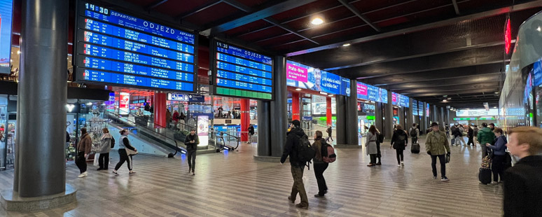
Railway Stations are massive things, definitely in the scales we as Lego Trainheads are building. A great example is Cale’s post about the PennLUG Lines, which shows that a Main Railway station easily rivals with its Staging Yard when it comes to size. However, that doesn’t mean you should not try building one. And thanks to The Lego Company (TLC), there is now a great example you can visit, as long as you are willing to travel to Kladno, Czech Republic. More specifically, we are talking about a model of Praha hlavní nádraží, the main Railway Station of Prague.
Thanks to a link shared on the Lego Train Fan Club page over at Facebook which caught my eye, I started to do some more research to find out as much as I could about this Diorama. There is a good reason for that: Having lived in Prague for two years and being in that station on almost weekly basis, it’s very close to me. Everything that makes Praha Hl.N. the station I love is there: The old station building, the Magistrala (the highway in front of the Railway Station), the new railway station and its interior (visible in front of the highway), the metro, and the actual double canopy above the tracks.
It turns out it’s not only a great model, but it even has running trains (one Shunter, one Main Line Locomotive which is about to couple with a rake of Intercity coaches, and a Metro!), moving elevators, lights… You name it, it’s there!
With Elroy’s articles on Matson’s Landing, and the A/D Track concept, as well as the the Track Geometry article, it seems we have a bit of a theme running right now with train layout design. I too am working on some layout planning, but unlike Elroy’s smaller, personal layout, I’m working on layout designs for my club, PennLUG. And since this is a different kind of beast from a home layout, I thought it would be great to illustrate all the planing that goes into a train layout like ours.
Before starting on the layout proper, I first want to define and build my motive power and rolling stock. The actual design of the track plan, including grades, number of cars spotted, and so on, will depend upon the equipment running over it. There are a few things to consider before beginning:
Scale – Six-wide or Eight-wide? I used to build six-wide trains, but I’ve come to enjoy the detail that can be added to the larger eight-wide trains. Six-wide would make for a smaller, more portable layout, but eight-wide allows for more space for batteries and motors.
Era – Most logging operations that are modeled seem to fall into the late 19th or early 20th centuries. Choosing a specific year, or year range, will help narrow down what kind of equipment to build.
Location – What part of the world should I aim for? Eastern or western United States? Maybe another part of the world?
Here’s what I first selected:
Scale – Eight-wide. I really want to be able to add detail. This will make for a larger layout, but I think it will be worth it in the end.
Era – I’m aiming for the turn of the 20th century. This seems to be the height of logging by rail type operations, and research material for this time period is plentiful.
Location – I live in northern New England in the United States, and logging operations were plentiful around here back in the day. This also opens up research material, as I can literally step outside of my door and look at scenery that was logged by rail at one time. One of my favorite hiking trails, in fact, runs along a portion of what used to be the Lye Brook Railroad, a small logging operation run from 1914 to 1919 by the Rich Lumber Company of Manchester, Vermont.[1]
Lye Brook Railroad as pictured in Volume 14 of the Walloomsack Review. Now a popular hiking trail.
With my basics defined, I started researching equipment. Generally, when one thinks about logging railroads, they think about small wood-fired geared steamers slowly crawling up steep grades, pulling strings of weather-worn log cars. The big three that immediately came to my mind where Shay, Climax, and Heisler.
“Building the Clishay” by Bob Maynard
A lot of builders put together Shay locomotives, with good reason. They look great while running! The exterior gear shafts provide some movement not seen on rod driven machines. I don’t consider myself to be a steam builder, or a Technic builder, though, so the gearing was a little off-putting for me. A Heisler, with its gear shaft underneath, might be workable, but, due to another of my other hobbies, I had Climax locomotives on my mind. In my Live Steam life, I’m working on a 1/8th scale “Clishay” locomotive. Billed as a cross between a Shay and a Climax, the Clishay[2] screams “small logging operation”. I love the hand-built look of it, and since the gearing is pretty simple, I thought it would lend itself well to a LEGO® design. The basic layout is similar to a Class A Climax with a vertical boiler. This, then, was where I began my prototype research.
In the next installment of this series, I’ll talk about the Climax designs that I looked at, and where I am currently with the build.
Just like our big sister from which we draw part of our inspiration (and part of our name), the Brick Model Railroader will have a recurring item where we (re)-visit layouts. For inspiration, to draw inspiration from, but also to showcase all the great stuff that has already been displayed across the world and had an impact on the Lego Train Hobby. Without wasting any more time, we would like to present our readers with the first showcased layout: Ararat 1972.
Ararat 1972 – front by Timothy Gould and Mike Pianta
I mean, just look at it. You wouldn’t say from a distance that this is build with Lego bricks, do you? So let us dive a little bit deeper in this layout and learn why this is such a great piece of work.
This website uses cookies to improve your experience. We'll assume you're ok with this, but you can opt-out if you wish. Cookie settingsACCEPT
Privacy & Cookies Policy
Privacy Overview
This website uses cookies to improve your experience while you navigate through the website. Out of these cookies, the cookies that are categorized as necessary are stored on your browser as they are essential for the working of basic functionalities of the website. We also use third-party cookies that help us analyze and understand how you use this website. These cookies will be stored in your browser only with your consent. You also have the option to opt-out of these cookies. But opting out of some of these cookies may have an effect on your browsing experience.
Necessary cookies are absolutely essential for the website to function properly. This category only includes cookies that ensures basic functionalities and security features of the website. These cookies do not store any personal information.
Any cookies that may not be particularly necessary for the website to function and is used specifically to collect user personal data via analytics, ads, other embedded contents are termed as non-necessary cookies. It is mandatory to procure user consent prior to running these cookies on your website.


 3rd party SBrick, approx 8x available power output in a smaller footprint


#/media/File:Praha,_Hlavn%C3%AD_n%C3%A1dra%C5%BE%C3%AD,_n%C3%A1stupi%C5%A1t%C4%9B,_odjezd_vlaku.JPG)
You must be logged in to post a comment.